![]()
| Wizard sizing / Velocity diagram |
Velocity diagram
Input a reference speed. There are two input methods. One is minimum input and the other is detailed input.Details for the Minimum Input and Detailed Input are shown below.
[Operation Procedure]
[Screen Structure]
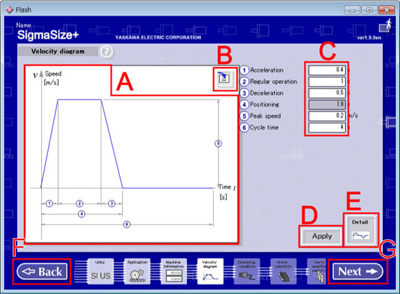
Velocity diagram Screen (Minimum Input)
Velocity diagram Preview
Displays the set velocity diagram of a reference speed.
In an initial status, default values are displayed.
Units of each axis are displayed units were set with Unit.
Data Load button
Loads a reference speed value from saved data.
The loaded data is converted to the current setting unit.
The converted data may be affected according to the roundoff error in unit conversion.
The loaded data may differ because it rounds off by the 4th place of the decimal point of index expression when unit conversion are carried out.
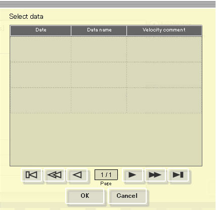
Load data dialogue
Select a data for loading, and then, click a [OK] button.
Data Input Column
Set a speed reference value.
Input items are different by selected application.
In addition, units of each item in the columns are displayed units were set with Unit.
In an initial status, default values are displayed.
When you selected anything other than vertical application with Application or loaded the data that is selected anything other than vertical application with "Velocity diagram".| Item | Explanation | Range which can be inputted |
| Acceleration | Display/Input acceleration time. | Larger than 0 and less than 1.0e+025 |
| Regular operation | Display/Input regular operating time. | 0 or more and less than 1.0e+025 |
| Deceleration | Display/Input deceleration time. | Larger than 0 and less than 1.0e+025 |
| Positioning | Calc and Display positioning time. | Automatically calculated in re-drawing. |
| Peak speed | Display/Input peak time. | Larger than 0 and less than 1.0e+025 |
| Cycle time | Display/Input cycle time. | Larger than 0 and less than 1.0e+025 |
When a vertical mechanism is selected on the machine information screen or
load a data for vertical mechanism on the velocity diagram.
| Item | Explanation | Range which can be inputted |
| Normal acceleration | Display/Input Normal acceleration time. | Larger than 0 and less than 1.0e+025 |
| Regular operation | Display/Input regular operation time. | 0 or more and less than 1.0e+025 |
| Normal deceleration | Display/Input Normal deceleration time. | Larger than 0 and less than 1.0e+025 |
| Normal positioning | Calc and Display Normal positioning time. | Automatically calculated in re-drawing. |
| Normal peak speed | Display/Input Normal positioning time. | Larger than 0 and less than 1.0e+025 |
| Normal cycle time | Display/Input Normal cycle time. | Larger than 0 and less than 1.0e+025 |
| Reverse acceleration | Display/Input Reverse acceleration time. | Larger than 0 and less than 1.0e+025 |
| Reverse regular operation | Display/Input Reverse regular operation time. | 0 or more and less than 1.0e+025 |
| Reverse deceleration | Display/Input Reverse deceleration time. | Larger than 0 and less than 1.0e+025 |
| Reverse positioning | Calc and Display Reverse positioning time. | Automatically calculated in re-drawing. |
| Reverse peak speed | Display/Input Reverse peak speed. | Larger than -1.0e+025 and smaller than 0 |
| Reverse cycle time | Display/Input Reverse cycle time. | Larger than 0 and less than 1.0e+025 |
| Item | Limit |
|---|---|
| Regular operation time Positive regular operation time negative regular operation time | 0 or more and less than 1.0e+025 |
| Others | Larger than 0 and less than 1.0e+025 |
Apply button
Verifies input value and redraws a velocity diagram.
Detailed Input button
Switches input method to the "Detailed Input".
Back button
Returns to the Machine information.
Next button
Checks input data, and then advances to the Operating condition.
[Operation Procedure]
[Screen Structure]
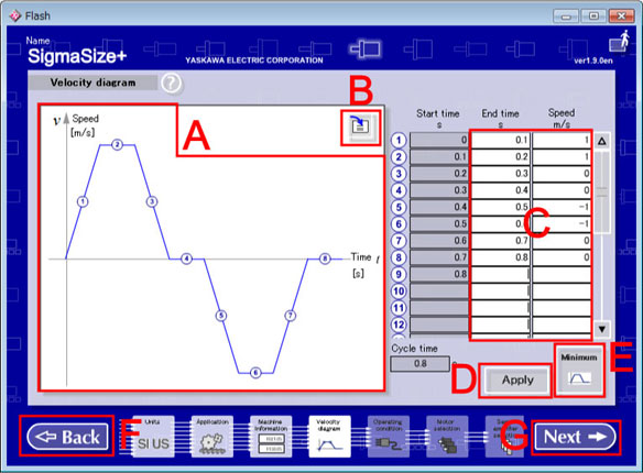
Velocity diagram Screen (Detailed Input)
Velocity Diagram Preview
Displays a set velocity diagram of a reference speed.
In an initial status, default values are displayed.
Units of each axis are displayed units were set with Unit.
Data Load button
Refer to Minimum Input
Data Input Column
Enter an end time and attainment speed.
The start time and cycle time is automatically calculated.
Input up to 40 digits is allowed.
When data is read or speed instructions are already set up, the value at that time is displayed.
Decide inputted values and advances to the Operation condition to click [Next].
* When input velocity from positive to negative (negative to positive), input 0 between positive and negative (negative and positive).
Apply button
Verifies the input value and redraws a velocity diagram.
Minimum Input button
Switches input method to the Minimum Input.
Back button
Returns to the Machine information.
Next button
Checks input data, and then advances to the Operating condition.
| Table of Contents |