![]()
| Wizard sizing / Machine information |
Machine information
The Machine information regarding the selected application is input.
[Operation Procedure]
[Screen Structure]
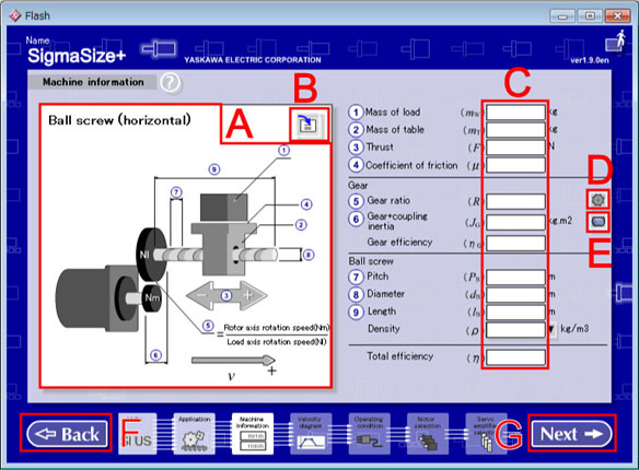
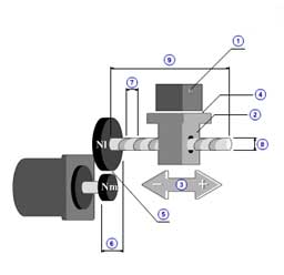
Machine information Screen (Ball Screw <horizontal>)
Application Preview
A selected application is zoomed in.
Load Data button
The value of the Machine information is loaded from saved data.
The data loaded is converted to the current set unit.
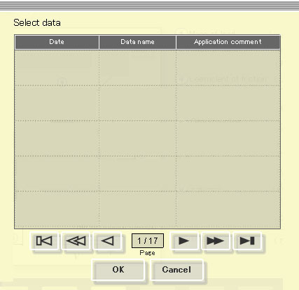
Load data dialogue
Data list
Data is displayed from the latest one at the date.
Click and select the following page button if necessary.
Select the data loaded then click "OK".
Goes to the previous screen without loading when click a "Cancel".
Data Input Column
In init state, all columns are blank.
When data is read or hold, the value at that time is displayed.
The number of maximum input beams of each input column is 12 figures(include such as a mark and a decimal point).
Example
Possible :1.0,-1.0,1.2345678912,-1.234567891,1.0e+100 etc.
Impossible;:1.00000000000,-1000000000,1.23456789123,1.000000e+001 etc.
Transmission calculation button
The Transmission calculation window is open.
*Displays beside the gear ratio input column.
Inertia calculation button
The Inertia calculation window is open.
*Displays beside the inertia input column.
Back button
Returns to the Application.
Next button
Advances to the Velocity diagram.
| Constants | |
| Gravity | g |
| Circular constant | π |
Input without Mechanism parameter | |
| Rotary type motor | |
| Rotor moment of ienrtia | JM |
| Motor option moment of inertia | JMO |
Linear type motor | |
| Moving coil mass | mM |
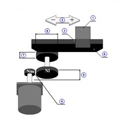
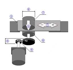
Ball screw (horizontal) [Back]
|
1 | Mass of load( mW ) |
| 2 | Mass of table( mT ) | |
| 3 | Thrust( F ) | |
| 4 | Coefficient of friction( μ ) | |
| 5 | Gear ratio( R ) | |
| 6 | Gear + coupling inertia( JG ) | |
| Gear efficiency( ηG ) | ||
| 7 | Pitch( PB ) | |
| 8 | Diameter( dB ) | |
| 9 | Length( lB ) | |
| Density( ρ ) | ||
| Total efficiency( η ) |
| Frictional force | FFR | = μ ( mW + mT )g | (N) |
| Constant external force | FC | = F | (N) | Moment of inertia component |
| Mechanism moment of inertia (Ball screw) | JMC | = πρB lB dB4 / ( 32 R 2 ) | (kg.m2) |
| Load mass moment of inertia | JW | = (mW + mT )( Kvn / 2π )2 | (kg.m2) |
| Load moment of inertia | JL | = JMC + JG + JW | (kg.m2) |
| Total load moment of inertia | JA | = JL + JM + JMO | (kg.m2) |
| * | Kvn | = PB / R | (m/rev) | Torque component |
| Torque by friction | TFR | = FFR Kvn / ( 2π ) | (N.m) |
| Constant torque | TC | = FC Kvn / ( 2π ) | (N.m) |
| Torque by force from forward | TFW | = 0 | (N.m) |
| Torque by force from backward | TBW | = 0 | (N.m) |
Timing belt (horizontal) [Back]
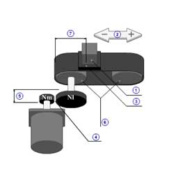
|
1 | Mass of load( mW ) |
| 2 | Thrust( F ) | |
| 3 | Coefficient of friction( μ ) | |
| 4 | Gear ratio( R ) | |
| 5 | Gear + coupling inertia( JG ) | |
| Gear efficiency( ηG ) | ||
| 6 | Pulley inertia( JP ) | |
| 7 | Pulley diameter( dP ) | |
| Total efficiency( η ) |
| Friction force | FFR | = μ mW g | (N) |
| Constant external force | FC | = F | (N) | Momemnt of inertia component |
| Mechanism moment of inertia (Pulley) | JMC | = JP / R 2 | (kg.m2) |
| Load mass moment of inertia | JW | = mW ( Kvn / 2π )2 | (kg.m2) |
| Load moment of inertia | JL | = JMC + JG + JW | (kg.m2) |
| Total load moment of inertia | JA | = JL + JM + JMO | (kg.m2) |
| * | Kvn | = π dP / R | (m/rev) |
Torque component | |||
| Torque by friction | TFR | = FFR Kvn / ( 2π ) | (N.m) |
| Consntant torque | TC | = FC Kvn / ( 2π ) | (N.m) |
| Torque by force from forward | TFW | = 0 | (N.m) |
| Torque by force from backward | TBW | = 0 | (N.m) |
Rack & pinion (horizontal) [Back]
|
1 | Mass of load( mW ) |
| 2 | Thrust( F ) | |
| 3 | Coefficient of friction( μ ) | |
| 4 | Gear ratio( R ) | |
| 5 | Gear + coupling inertia( JG ) | |
| Gear efficiency( ηG ) | ||
| 6 | Mass of rack( mR ) | |
| 7 | Pinion inertia( JPIN ) | |
| 8 | Pinion diameter( dPIN ) | |
| Total efficiency( η ) |
| Frictional force | FFR | = μ ( mW + mR )g | (N) |
| Consntant external force | FC | = F | (N) | Moment of inertia component |
| Mechanism moment of inertia (Pinion) | JMC | = JPIN / R 2 | (kg.m2) |
| Load mass moment of inertia | JW | = ( mW + mR )( Kvn / 2π )2 | (kg.m2) |
| Load moment of inertia | JL | = JMC + JG + JW | (kg.m2) |
| Total load moment of inertia | JA | = JL + JM + JMO | (kg.m2) |
| * | Kvn | = π dPIN / R | (m/rev) |
Torque component | |||
| Torque by friction | TFR | = FFR Kvn / ( 2π ) | (N.m) |
| Constant torque | TC | = FC Kvn / ( 2π ) | (N.m) |
| Torque by force from forward | TFW | = 0 | (N.m) |
| Torque by force from backward | TBW | = 0 | (N.m) |
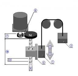
|
1 | Mass of load( mW ) |
| 2 | Mass of table( mT ) | |
| 3 | Mass of counter( mWC ) | |
| 4 | Thrust in ascending( FVU ) | |
| 5 | Thrust in descending( FVD ) | |
| 6 | Gear ratio( R ) | |
| 7 | Gear + coupling inertia( JG ) | |
| Gear efficiency( ηG ) | ||
| 8 | Pitch( PB ) | |
| 9 | Diameter( dB ) | |
| 10 | Length( lB ) | |
| Density( ρ ) | ||
| Total efficiency( η ) | ||
*Reference
| ||
| Frictional force | FFR | = 0 | (N) |
| Constant external force(Thrust + Gravity) | FC | = - ( mW + mT - mWC )g | (N) |
| Force from forward | FFW | = FVU | (N) |
| Force from backward | FBW | = FVD | (N) | Moment of inertia component |
| Mechanism moment of inertia (Ball screw) | JMC | = π ρB lB dB4 / ( 32 R 2 ) | (kg.m2) |
| Load mass moment of inertia | JW | = ( mW + mT + mWC )( Kvn / 2π )2 | (kg.m2) |
| Load moment of inertia | JL | = JMC + JG + JW | (kg.m2) |
| Total load moment of inertia | JA | = JL + JM + JMO | (kg.m2) |
| * | Kvn | = PB / R | (m/rev) |
Torque component | |||
| Torque by friction | TFR | = FFR Kvn / ( 2π ) | (N.m) |
| Constant torque | TC | = FC Kvn / ( 2π ) | (N.m) |
| Torque by force from forward | TFW | = FFW Kvn / ( 2π ) | (N.m) |
| Torque by force from backward | TBW | = FBW Kvn / ( 2π ) | (N.m) |
|
1 | Mass of load( mW ) |
| 2 | Mass of counter( mWC ) | |
| 3 | Thrust in ascending( FVU ) | |
| 4 | Thrust in descending( FVD ) | |
| 5 | Gear ratio( R ) | |
| 6 | Gear + coupling inertia( JG ) | |
| Gear efficiency( ηG ) | ||
| 7 | Pulley inertia( JP ) | |
| 8 | Pulley diameter( dP ) | |
| Total efficiency( η ) |
| Frictional force | FFR | = 0 | (N) |
| Constant external force(Thrust+Gravity) | FC | = - ( mW + mT - mWC )g | (N) |
| Torque by force from forward | FFW | = FVU | (N) |
| Torque by force from backward | FBW | = FVD | (N) | Moment of inertia component |
| Mechanism moment of inertia (Pulley) | JMC | = π ρB lB dB4 / ( 32 R 2 ) | (kg.m2) |
| Load mass moment of inertia | JW | = ( mW + mT + mWC )( Kvn / 2π )2 | (kg.m2) |
| Load moment of inertia | JL | = JMC + JG + JW | (kg.m2) |
| Total load moment of inertia | JA | = JL + JM + JMO | (kg.m2) |
| * | Kvn | = PB / R | (m/rev) |
Torque component | |||
| Torque by friction | TFR | = FFR Kvn / ( 2π ) | (N.m) |
| Constant torque | TC | = FC Kvn / ( 2π ) | (N.m) |
| Torque by force from forward | TFW | = FFW Kvn / ( 2π ) | (N.m) |
| Torque by force from backward | TBW | = FBW Kvn / ( 2π ) | (N.m) |
Rack & pinion (Vertical) [Back]
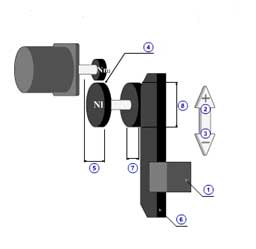
|
1 | Mass of load( mW ) |
| 2 | Thrust in ascending( FVU ) | |
| 3 | Thrust in descending( FVD ) | |
| 4 | Gear ratio( R ) | |
| 5 | Gear + coupling inertia( JG ) | |
| Gear efficiency( ηG ) | ||
| 6 | Mass of rack( mR ) | |
| 7 | Pinion inertia( JPIN ) | |
| 8 | Pinion diameter( dPIN ) | |
| Total efficiency( η ) |
| Frictional force | FFR | = 0 | (N) |
| Constant force(Thrust+gravity) | FC | = - ( mW + mR )g | (N) |
| Force from forward | FFW | = FVU | (N) |
| Force from backward | FBW | = FVD | (N) | Moment of inertia component |
| Mechanism moment of inertia (Pinion) | JMC | = JPIN / R 2 | (kg.m2) |
| Load mass moment of inertia | JW | = ( mW + mR )( Kvn / 2π )2 | (kg.m2) |
| Load moment of inertia | JL | = JMC + JG + JW | (kg.m2) |
| Total load moment of inertia | JA | = JL + JM + JMO | (kg.m2) |
| * | Kvn | = π dPIN / R | (m/rev) |
Torque component | |||
| Torque by friction | TFR | = FFR Kvn / ( 2π ) | (N.m) |
| Constant torque | TC | = FC Kvn / ( 2π ) | (N.m) |
| Torque by force from forward | TFW | = FFW Kvn / ( 2π ) | (N.m) |
| Torque by force from backward | TBW | = FBW Kvn / ( 2π ) | (N.m) |
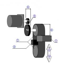
|
1 | Tension( F ) |
| 2 | Press( FP ) | |
| 3 | Coefficient of friction( μ ) | |
| 4 | Gear ratio( R ) | |
| 5 | Gear + coupling inertia( JG ) | |
| Gear efficiency( ηG ) | ||
| 6 | Driving roller inertia( JR1 ) | |
| 7 | Driven roller inertia( JR2 ) | |
| 8 | Driving roller diameter( dR ) | |
| Total efficiency( η ) | ||
*Reference
| ||
| Frictional force | FFR | = μ FP | (N) |
| Constant external force | FC | = F | (N) | Moment of inertia component |
| Mechanism moment of inertia (Roller) | JMC | = ( JR1 + JR2 ) / R 2 | (kg.m2) |
| Load mass moment of inertia | JW | = 0 | (kg.m2) |
| Load moment of inertia | JL | = JMC + JG + JW | (kg.m2) |
| Total load moment of inertia | JA | = JL + JM + JMO | (kg.m2) |
| * | Kvn | = π dR / R | (m/rev) |
Torque component | |||
| Torque by friction | TFR | = FFR Kvn / ( 2π ) | (N.m) |
| Constant torque | TC | = FC Kvn / ( 2π ) | (N.m) |
| Torque by force from forward | TFW | = 0 | (N.m) |
| Torque by force from backward | TBW | = 0 | (N.m) |
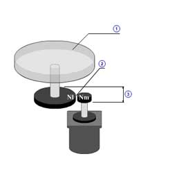
|
1 | Load inertia( JWL ) |
| Friction torque( TFL ) | ||
| 2 | Gear ratio( R ) | |
| 3 | Gear + coupling inertia( JG ) | |
| Gear efficiency( ηG ) | ||
| Total efficiency( η ) |
| Mechanism moment of inertia (Rotor) | JMC | = JWL / R 2 | (kg.m2) |
| Load mass moment of inertia | JW | = 0 | (kg.m2) | Moment of inertia component |
| Load moment of inertia | JL | = JMC + JG + JW | (kg.m2) |
| Total load moment of inertia | JA | = JL + JM + JMO | (kg.m2) |
| * | Kvn | = 1 / R | |
Torque component | |||
| Torque by friction | TFR | = TFL Kvn | (N.m) |
| Consntant torque | TC | = 0 | (N.m) |
| Torque by force from forward | TFW | = 0 | (N.m) |
| Torque by force from backward | TBW | = 0 | (N.m) |
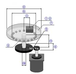
|
1 | Load inertia( JWL ) |
| 2 | Mass of load( mWL ) | |
| 3 | Radius of load mass( rWL ) | |
| 4 | Coefficient of friction( μ ) | |
| 5 | Gear ratio( R ) | |
| 6 | Gear + coupling inertia( JG ) | |
| Gear efficiency( ηG ) | ||
| 7 | Mass of rotation table( mT ) | |
| 8 | Rotation table diameter( dT ) | |
| 9 | Holding shaft diameter( dF ) | |
| 10 | Main shaft diameter( dS ) | |
| 11 | Main shaft length( lS ) | |
| Main shaft density( ρS ) | ||
| Total efficiency( η ) |
| Mechanism moment of inertia (Table + shaft) | JMC | = (π ρS lS dS4 / 32 + mT dT2 / 8 ) / R 2 | (kg.m2) |
| Load mass moment of inertia | JW | = ( JWL + mWL rWL2 ) / R 2 | (kg.m2) | Moment of inertia component |
| Load moment of inertia | JL | = JMC + JG + JW | (kg.m2) |
| Total load moment of inertia | JA | = JL + JM + JMO | (kg.m2) |
| * | Kvn | = 1 / R | |
Torque component | |||
| Torque by friction | TFR | = μ ( mWL + mT )g ( dF / 2 ) Kvn | (N.m) |
| Constant torque | TC | = 0 | (N.m) |
| Torque by force from forward | TFW | = 0 | (N.m) |
| Torque by froce from backward | TBW | = 0 | (N.m) |
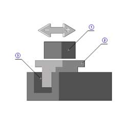
|
1 | Mass of load( mW ) |
| 2 | Mass of table( mT ) | |
| 3 | Friction force( FFR ) | |
| Force margin( KM ) | ||
| Total efficiency( η ) | ||
|
* Friction force( FFR ) Please include the following thrust by which coefficient of friction is considered to the friction force. 1.The load required thrust by which the friction coefficient of machine part is considered, such as a linear guide. 2.Mass of linear motor movable required thrust by which the friction coefficient of machine part is considered, such as a linear guide. 3.The power-of-absorption part required thrust of the linear motor with core by which the friction coefficient of machine part is considered, such as linear guide. * Force margin( KM ) This is a coefficient assuming the case which increases required force to accelerate or decelerate, on the structure of a machine. Input 1 or more value by the inertia between a moving coil and the center of gravity of load. Force to accelerate or decelerate is calculated as F = KM m a. |
||
| Mass of load | mL | = mW + mT | (kg) |
| Total mass of load | mA | = mL + mM | (kg) |
| Section speed pattern | i | = 1 .. n | |
| Section time | ti | (s) | |
| Section speed | vi | (m/s) |
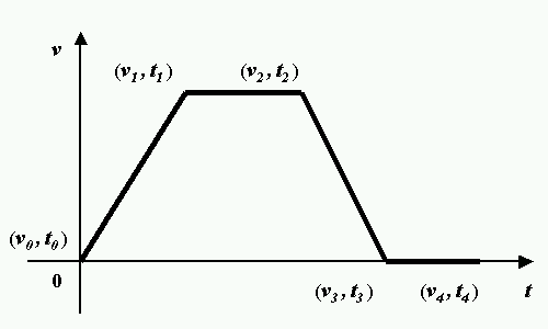 |
| Example for velocity diagram |
| Section rotation speed difference | nMdi | = ( vi - vi-1 ) / Kvn | (s-1) |
| Section acceleration torque | TAi | = JA ( 2π nMdi / ( ti - ti-1 ) ) | (N.m) |
| Section torque | Ti | (N.m) | |
| Normal ( nMi > 0 OR nMi = 0, nMi-1 > 0 ) | Ti | = TAi - TC - TFW + TFR | (N.m) |
| Reverse ( nMi < 0 OR nMi = 0, nMi-1 < 0 ) | Ti | = TAi - TC - TBW - TFR | (N.m) |
| Stopping ( nMi = 0) | |||
| | TC | > TFR | |||
| TC > 0 | Ti | = - TC + TFR | (N.m) |
| TC < 0 | Ti | = - TC - TFR | (N.m) |
| | TC | <= TFR | Ti | = 0 | (N.m) |
| Effective torque | TRMS | = √( ∑ ni=1 Ti 2 ( ti - ti-1 ) / tn ) | (N.m) |
| | |||
| Required force(Linear motor type) | |||
| Section acceleration force | FAi | = KM mA ( vi - vi-1 ) / ( ti - ti-1 ) | (N) |
| Section force | Fi | (N) | |
| Normal (vi > 0 OR vi = 0, vi-1 > 0 ) | Fi | = FAi + ( FFR / η ) | (N) |
| Reverse (vi < 0 OR vi = 0, vi-1 < 0 ) | Fi | = FAi + ( - FFR / η ) | (N) |
| Stopping (vi = 0, vi = 0 ) | Fi | = 0 | (N) |
| Effective force | FRMS | = √( ∑ ni=1 Fi 2 ( ti - ti-1) / tn ) | (N) |
| Table of Contents |